Ohm's Law · Visualised
The Electrical & Hydraulic Analogy
Two circuits, one law. Drive both with the same controls and watch flow respond to pressure and constriction.
Electrical circuitcharge in a wire
Hydraulic circuitwater in a pipe
Reference · Electrical Theory
Ohm's Law
History, Mathematical Formulation, and Applications
1. Introduction
Electricity is governed by a small number of quantitative relationships that connect the fundamental measurable quantities of a circuit. Among these, the relationship between voltage, current, and resistance is the most widely used in everyday electrical and electronic work. It allows an engineer or student to predict how much current will flow when a known voltage is applied to a component of known resistance, or conversely to determine the resistance required to achieve a desired current.
Although the relationship is elementary, its importance is difficult to overstate. It underlies the design of virtually every circuit, from the current-limiting resistor in front of a light-emitting diode to the analysis of power distribution networks. This article introduces the law in its historical context, explains each of its formulas in detail, and demonstrates the breadth of its practical use.
2. Historical Background
The law is named after Georg Simon Ohm (1789–1854), a German physicist and mathematician who taught at the Jesuit Gymnasium of Cologne. Working with wires of different lengths and cross-sections, and using a thermocouple as a comparatively stable source of electromotive force, Ohm carried out careful experiments to determine how the current in a circuit depended on the conductor used.
Ohm published his findings in 1827 in a treatise titled Die galvanische Kette, mathematisch bearbeitet (“The Galvanic Circuit Investigated Mathematically”). In it he expressed the relationship that would later carry his name and framed it in a rigorous mathematical form, drawing an analogy to the emerging theory of heat conduction developed by Joseph Fourier.
Initial reception of Ohm's work in Germany was cool, and recognition came slowly. Over time, however, the significance of his contribution was widely acknowledged. In 1841 the Royal Society of London awarded him the Copley Medal, and his name was later adopted for the SI unit of electrical resistance, the ohm (symbol Ω), cementing his lasting place in the history of physics.
3. Mathematical Formulation
3.1 The fundamental relationship
In its most familiar modern form, Ohm's law states that the current through a conductor between two points is directly proportional to the voltage across the two points. Introducing the constant of proportionality known as resistance, the relationship is written as:
where V is the voltage (potential difference) across the conductor, measured in volts (V); I is the current flowing through it, measured in amperes (A); and R is the resistance of the conductor, measured in ohms (Ω).
3.2 Rearranged forms
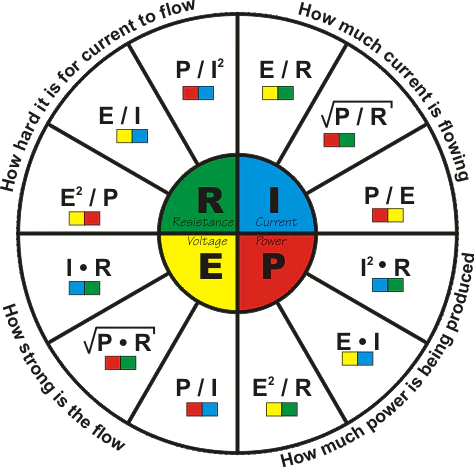
Because the relationship is a simple algebraic equation, it can be rearranged to solve for whichever quantity is unknown. The three equivalent forms are:
These three expressions are used constantly in circuit analysis. If any two of the quantities are known, the third can be found immediately. A common mnemonic arranges the three symbols in a triangle so that covering the unknown reveals the correct arrangement of the other two.
3.3 Resistance and material properties
The resistance of a uniform conductor is itself determined by the material and geometry of the object. It is given by R = ρL / A, where ρ (rho) is the resistivity of the material, L is the length of the conductor, and A is its cross-sectional area. A longer or thinner conductor therefore has greater resistance, while a material of low resistivity such as copper conducts readily.
3.4 Power relationships
Combining Ohm's law with the definition of electrical power (the rate at which energy is delivered or dissipated) yields a family of equally useful equations. Starting from P = V × I and substituting the relationships above gives:
Here P is power in watts (W). These forms are indispensable when estimating the heat a resistor must dissipate, since power appearing as heat can damage components if it exceeds their rated limits.
4. The Hydraulic Analogy
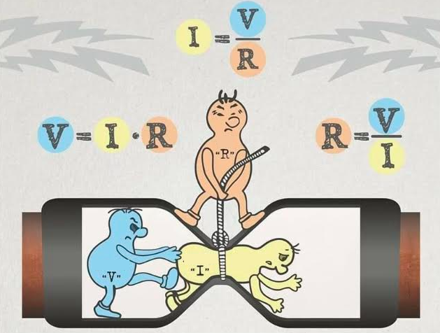
Because voltage, current, and resistance are not directly visible, many learners find it helpful to picture an electrical circuit as a closed system of water pipes. The hydraulic analogy maps each electrical quantity onto a familiar mechanical counterpart, making the behaviour described by Ohm's law intuitive without changing any of the underlying mathematics.
In this picture, voltage corresponds to water pressure: it is the push that drives movement but is not itself the movement. Electric current corresponds to the rate of water flow — how much water passes a given point each second. Resistance corresponds to how narrow or obstructed the pipe is; a constricted pipe permits less flow for the same pressure, just as a higher resistance permits less current for the same voltage. The correspondences are summarised below.
| Electrical quantity | Hydraulic counterpart | Shared role |
|---|---|---|
| Voltage (V) — volts | Pressure difference — pushes water | The driving force that motivates flow |
| Current (I) — amperes | Flow rate — volume of water per second | The amount of “stuff” moving past a point |
| Resistance (R) — ohms | Pipe narrowness / friction | The opposition that limits how much flows |
| Conductor / wire | Pipe | The channel through which flow travels |
| Battery / source | Pump or raised reservoir | The element that sustains the driving force |
| Power (P) — watts | Rate of hydraulic work done | Energy delivered per unit time |
The analogy also reproduces the structure of the equation itself. Writing Ohm's law as I = V ÷ R reads naturally as “flow increases when pressure rises and decreases when the pipe is more constricted.” Doubling the pressure across a fixed pipe doubles the flow, exactly as doubling the voltage across a fixed resistor doubles the current. A pump maintaining pressure is the counterpart of a battery maintaining voltage, and the work the pump does per second corresponds to electrical power.
5. Conditions and Limitations
Ohm's law is an empirical relationship rather than a fundamental law of nature, and it holds accurately only for so-called ohmic materials, in which resistance remains essentially constant over a range of applied voltages. Many metallic conductors at constant temperature behave in this way, producing a straight-line (linear) relationship between voltage and current.
A number of important components do not obey the law. Diodes, transistors, filament lamps, and thermistors are non-ohmic: their resistance changes with voltage, current, or temperature, so a plot of current against voltage is curved rather than straight. For a filament lamp, for example, the resistance rises as the filament heats, while for a semiconductor diode the current increases sharply only after a threshold voltage is reached. In these cases Ohm's law can still be applied locally to describe behaviour at a specific operating point, but not as a single fixed proportionality.
Temperature dependence is a further caveat. Because resistivity generally varies with temperature, the resistance measured under one set of conditions may differ from that under another. Careful measurements, such as those Ohm himself performed, must therefore control for temperature to obtain consistent results.
6. Applications and Usages
The practical reach of Ohm's law extends across essentially all of electrical and electronic engineering. The table below summarises several representative applications and the form of the equation typically used in each.
| Field / Application | How Ohm's Law is used | Typical quantity solved |
|---|---|---|
| Circuit design | Selecting resistor values to set currents and voltages at nodes | R = V / I |
| Current limiting | Sizing series resistors for LEDs and sensitive components | R = (Vs − Vf) / I |
| Power dissipation | Estimating heat generated so components are not overloaded | P = I²R |
| Sensor measurement | Converting resistance changes (thermistors, strain gauges) into voltage | V = I R |
| Fault diagnosis | Detecting shorts or opens from abnormal current or voltage readings | I = V / R |
| Electrical safety | Estimating fault currents to specify fuses and breakers | I = V / R |
Beyond these examples, the law is embedded in more advanced analytical frameworks. Kirchhoff's circuit laws, network theorems such as Thévenin's and Norton's, and the analysis of alternating-current circuits (where resistance generalises to impedance) all build upon the basic voltage–current–resistance relationship. Even in fields such as electrochemistry and bioelectrical measurement, the same proportionality provides a first approximation for how current responds to applied potential.
7. A Simple Worked Example
Consider a light-emitting diode that operates safely at a current of 20 milliamperes (0.020 A) and has a forward voltage drop of about 2 volts. If it is connected to a 5-volt supply, a series resistor is required to limit the current. The voltage that must appear across the resistor is the supply voltage minus the diode drop, namely 5 − 2 = 3 volts.
Applying R = V ÷ I gives R = 3 V ÷ 0.020 A = 150 Ω. The power dissipated in the resistor is P = I²R = (0.020)² × 150 ≈ 0.06 W, comfortably within the rating of a standard quarter-watt resistor. This short calculation illustrates how the core formula and its power companion are used together in routine design.
8. Conclusion
Ohm's law captures, in a single compact equation, the proportional relationship between voltage, current, and resistance that governs the behaviour of ordinary conductors. From its careful experimental origins in the work of Georg Simon Ohm to its ubiquitous use in modern circuit design, the law remains a cornerstone of electrical science. Understanding both its formulation and its limits allows engineers and students to reason confidently about circuits and to recognise where more sophisticated models are required.
References
- Encyclopædia Britannica. “Ohm's law — Physics.” https://www.britannica.com/science/Ohms-law
- Encyclopædia Britannica. “Georg Ohm — German Physicist.” https://www.britannica.com/biography/Georg-Ohm
- National Institute of Standards and Technology (NIST). “SI Units — Resistance and the Ohm.” https://www.nist.gov/pml/owm/metric-si/si-units
- HyperPhysics, Georgia State University. “Ohm's Law.” http://hyperphysics.phy-astr.gsu.edu/hbase/electric/ohmlaw.html
- MIT OpenCourseWare. “Circuits and Electronics (6.002).” https://ocw.mit.edu/courses/6-002-circuits-and-electronics-spring-2007/
- Khan Academy. “Ohm's Law — Circuit Analysis.” https://www.khanacademy.org/science/physics/circuits-topic
- Institute of Electrical and Electronics Engineers (IEEE). “Georg Simon Ohm — Engineering and Technology History Wiki.” https://ethw.org/Georg_Simon_Ohm
© 2026 Gallois Genootschap. All rights reserved.
This article is provided for general information only. While care has been taken in its preparation, Gallois Genootschap makes no warranty as to its accuracy or completeness and accepts no liability for any loss or damage arising from its use.
Parts of this article were prepared with the assistance of AI and reviewed by Gallois Genootschap, which holds editorial responsibility for its publication.